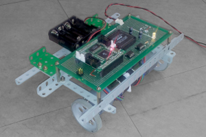
The robot is powered either by 4 x AA batteries or an external power source, as shown here.
The red LED indicates the system status.
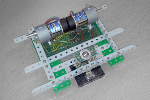
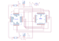
The frame is constructed from a Meccano (Erector) kit. A solder breadboard is used to wire all the modules together.
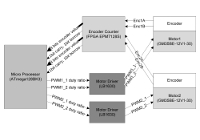
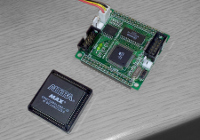
The robot has a Differential Drive configuration. Two DC motors with built-in gearbox and encoder are located at the front of the robot and a small metal ball caster at the rear provides balance. The software was written in C language on an Atmel ATmega128 microcontroller. Each motor is driven via a H-Bridge chip and PWM from the microcontroller. The encoder sensors are connected to a digital counter circuit implemented on an Altera EPM7128S PLD (Programmable Logic Device). The rotational position of each wheel is an 8-bit value that gets passed to the microcontroller.
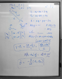
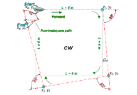
In order to measure the dead reckoning error, some initial experiments were conducted and the robot was able to trace a circle or square on a hard, flat surface with negligible error. The square obviously involves making turns in-place, with zero radius. However, these zero radius turns can result is larger heading error and so the Dubins path was more accurate over longer distances.
This was a team project with C. K. Jung & T. J. Kim.
|
[1] L. E. Dubins, “On Curves of Minimal Length with a Constraint on Average Curvature, and with
Prescribed Initial and Terminal Positions and Tangents”, American Journal of Mathematics, July 1957 |
